
Technical insight
Multi-Stage Rotor Axial Spacing: Face Gaps, Stage Pitch and Total Height
Keep total-height acceptance separate from drawing-defined stage pitch and face-to-face gaps. Before ordering, ask the design owner to identify the endpoints of each required distance and ask the inspection provider to explain how that distance will be evaluated. Agree a characteristic-to-report map before accepting a quotation described only as axial spacing checked.
By Geetai Precision
- Published
- Updated
The distance requirement
ASME’s public Y14.5 description covers the statement and interpretation of drawing and digital-model requirements, including datum-reference concepts. [3]
Ask which released document governs each distance. For stage pitch, request the corresponding feature or constructed reference on each named row; do not assume a center-to-center definition. For a face gap, identify the actual opposing surfaces and relevant regions. For total height, identify the end features and any excluded projections.
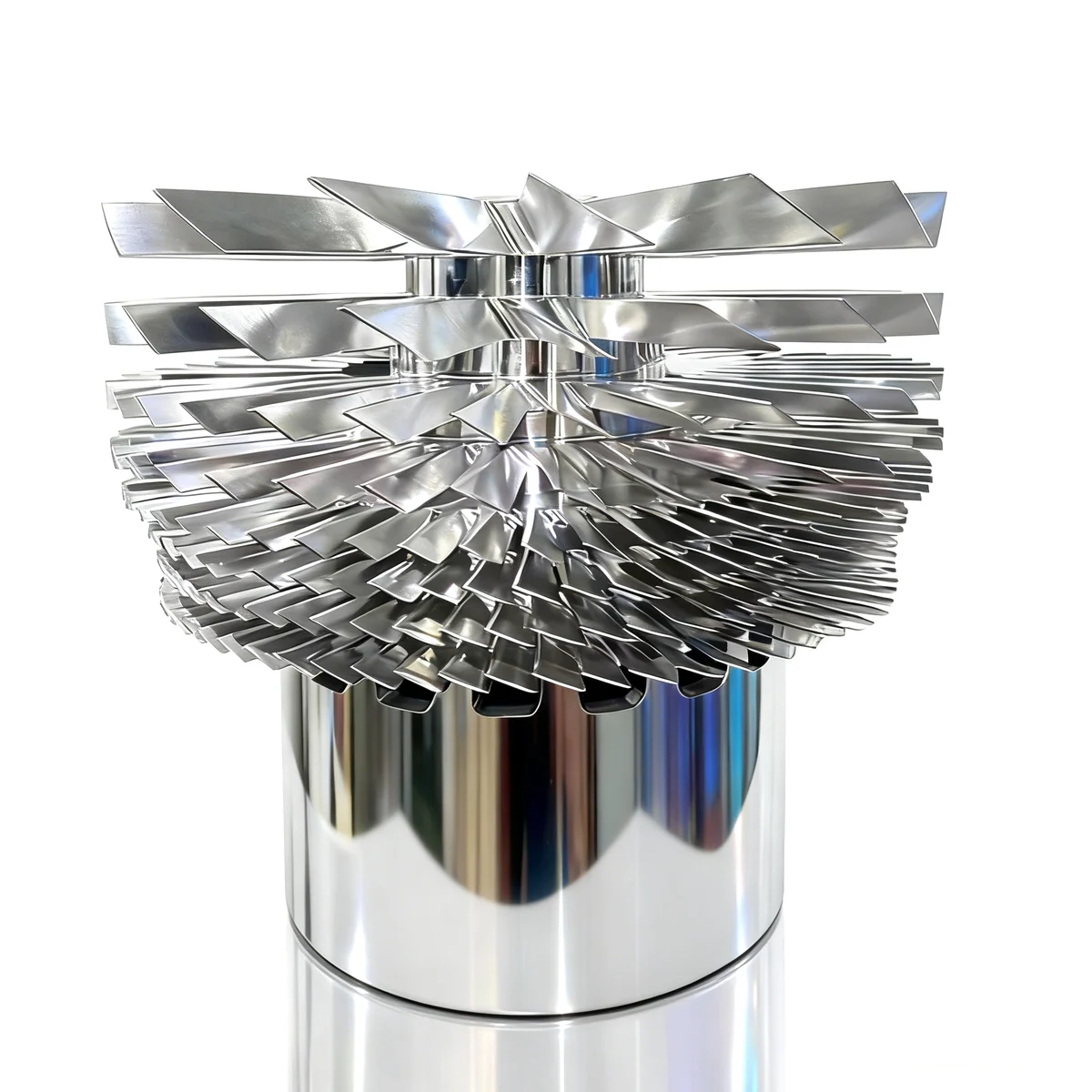
Use the supplied component image as a visual reference when discussing repeated rows. Obtain row identities and measurement surfaces from the controlled definition. Do not derive a stage count, axial dimension, mating-part clearance or operating approval from the picture.
Direction, projection and feature order
Hexagon’s PC-DMIS 2023.2 help describes projecting features into the current workplane for a 2D distance, with a stated exception for a distance perpendicular to a third feature defined as a plane. [1]
Its PC-DMIS 2020.2 help defines the 3D distance between two planes as the perpendicular distance from the first plane’s centroid to the second plane, with the second plane serving as the reference. [2]
These version-specific software examples illustrate why a distance label needs an evaluation definition. Ask the metrology reviewer to approve the direction or projection, input-feature order and reference required by the drawing. Do not select a software option solely because its name resembles the drawing note.
An axial-distance worksheet
| Requirement | Definition before order | Report mapping |
|---|---|---|
| Stage pitch | Identify the corresponding row features or constructed references and every required row pair. | Assign each required pair a characteristic ID and an approved distance definition. |
| Face-to-face gap | Mark both facing regions and any required section or evaluation location. | Name the report entry and whether the approved output concerns local gaps or another defined evaluation. |
| Total axial height | Identify both end features, the axial direction and any excluded projections. | Keep the overall-height entry separate from the individual row requirements. |
| Row position from a reference | Identify the specified origin feature and each required row feature. | Record the direction convention and map each row position to its drawing requirement. |
The inspection handoff
- Before quotation: attach the controlled drawing and model, mark each required axial distance, and nominate the design reviewer for ambiguous endpoints. Obtain clarification rather than translating a general spacing note into a supplier-selected dimension.
- Before inspection: ask the provider to return the characteristic list with feature IDs, surface regions, direction or projection, reference and proposed evaluation. Include the delivered processing condition and flag any surface that cannot be acquired as proposed.
- At program review: reconcile the selected input features and distance settings with that approved list. Ask the technical reviewer to resolve substituted features, constructed references or changed evaluation locations before accepting the affected method.
- At reporting: require each requested row pair or gap to link to its characteristic ID and reported value. Keep omitted checks visible. At receiving review, obtain an authorized disposition for missing or mismatched entries before closing those requirements.
For example, suppose a hypothetical report lists overall height while the order also requests a gap between two identified row faces. Keep the height result within its stated scope and request the missing gap evaluation. If the original acquisition lacks the required surfaces, ask for a revised acquisition plan. Do not infer the gap from the overall entry.
Quotation scope and approval boundaries
For a drawing-led rotor inquiry, provide the marked distance map, document revisions and requested report example. Use the rotor machining review and dimensional inspection coordination routes to agree the handoff responsibilities and quotation scope.
Inspection scope and documentation are defined during quotation according to drawing requirements and application needs.
Geetai coordinates drawing-led manufacturing through long-term partners without presenting partner facilities as Geetai-owned.
Keep component-distance acceptance separate from mating-assembly clearance, balancing and operating approval. Request those deliverables separately when the order requires them; an axial-distance report should close only the requirements it explicitly covers.
Frequently asked questions
A plane-distance result for a local face gap?
Ask the reviewer whether the proposed plane evaluation answers the specified local requirement. The cited 3D plane definition uses a centroid and reference plane; request the approved treatment of the actual facing regions before treating that output as the required gap.
Related review paths
More from Blog
References
- PC-DMIS 2023.2 — 2D Distance — Hexagon Manufacturing Intelligence. Accessed 2026-11-04T01:36:52.800Z.
- PC-DMIS 2020.2 — 3D Distance — Hexagon Manufacturing Intelligence. Accessed 2026-11-04T01:36:52.772Z.
- ASME Y14.5 — Dimensioning and Tolerancing — ASME. Accessed 2026-11-04T01:36:52.801Z.