
Technical insight
Rotor Hub Thread Gauging: What Acceptance Records Should Accompany the Part?
For a threaded rotor or impeller hub, request evidence against the thread requirement itself. A bore result or an overall dimensional pass should close only its stated scope. Before ordering, agree which thread characteristics will be assessed, which gauges or measurement methods apply, and what record accompanies the delivered condition.
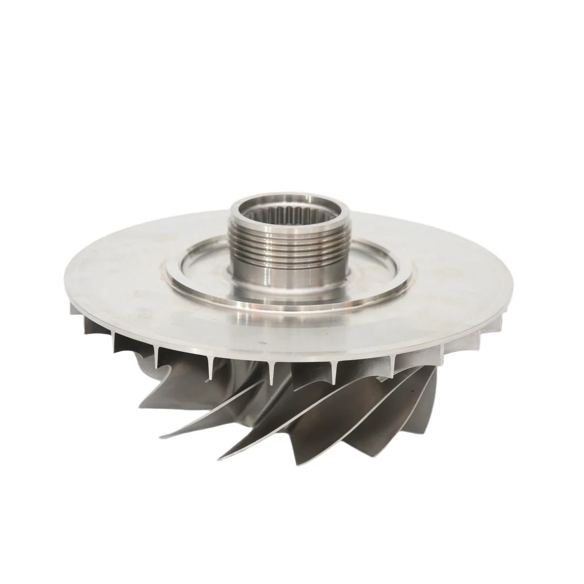
By Geetai Precision
- Published
- Updated
Separate the thread question from the bore result
ASME’s public B1.3 scope describes a gauging system as a selected set of thread characteristics and the gauges used to inspect them. Its scope addresses listed inch and metric thread families on internally and externally threaded products. [1]
Ask the technical reviewer to identify the thread designation, pitch or lead as applicable, specified thread class, handedness, required full-thread extent and governing specification edition. Use the released callout; do not select a thread family from the supplied photograph. Resolve an incomplete callout before accepting the gauging scope.
When a CMM record reports a smooth bore diameter or location, ask where the separate thread acceptance is documented. If a coordinate measurement method is proposed for thread characteristics, request its named coverage and technical approval. Judge the agreed method against the requirement rather than accepting or rejecting it by equipment name alone.
Match the evidence to the characteristic
Johnson Gage lists threaded ring gauges for external threads and threaded plug gauges for internal threads, with distinct GO and NOT GO functions. It separately lists plain cylindrical gauges for internal minor diameter. [2]
Its external and internal differential-inspection procedures distinguish pitch diameter, functional size and a separate major- or minor-diameter check. These are manufacturer-specific procedures, not a mandatory inspection sequence for every hub. [3][4]
Use those distinctions to ask what each proposed result establishes. Agree whether delivery needs recorded limit-gauge outcomes, measured values for selected characteristics, or both under the applicable specification. Do not request a numerical pitch-diameter value and then silently accept an undefined “thread OK” entry in its place.
The following approval worksheet is original purchasing guidance. The technical owner selects the actual checks, extent and acceptance criteria; the cited public pages do not supply a complete inspection plan for your component.
A thread-evidence approval worksheet
| Approval item | Request in the quotation | Decision if unresolved |
|---|---|---|
| Thread definition | Confirm the complete released callout and applicable specification edition. | Return missing class, direction or thread-extent information for design clarification. |
| Method coverage | Map each required thread characteristic to its proposed gauge or measurement method. | Obtain technical approval of any alternative and identify characteristics still uncovered. |
| Gauge outcome | Record the gauge identification, applicable designation and separate required outcomes. | Resolve a bare “thread passed” statement before closing the evidence review. |
| Delivery condition | Identify whether the check covers the condition before or after specified finishing. | Ask which checks must follow treatment or approved thread rework. |
| Release evidence | Link the thread result to the inspected item or agreed lot and the approved instruction. | Keep missing evidence or an adverse result open for the named reviewer’s disposition. |
From thread machining to release
Before machining, have the manufacturing and inspection reviewers agree the route for the called-out thread and access for the proposed check. Flag a shoulder, short thread or recessed feature where the reviewer needs to explain the usable checking extent. Purchasing should request that explanation rather than inventing a gauge design.
At the machining handoff, identify the part and thread feature, complete the specified edge work, and prepare it for the agreed inspection. Johnson Gage’s procedures require cleaning parts and gauging elements before inspection. Follow the approved method and applicable gauge instructions; this article does not prescribe cleaning chemistry or engagement force. [3][4]
If coating, plating or another specified finish follows, make the thread’s acceptance stage explicit in the order. Ask the responsible reviewer which checks are required in the delivered condition. Where the final check is unsuccessful, request a disposition before chasing, recutting or stripping the thread; keep any approved rework and subsequent checks linked to the same item.
Before shipment, reconcile the thread-evidence worksheet with the actual records. Retain the separate bore or other dimensional results for their own requirements. A missing thread record calls for clarification; an adverse thread result calls for technical disposition. Do not close either case using an unrelated passing dimension.
Prepare a quotation review
Send the controlled hub drawing and model, complete thread callout, required finishing stage and requested evidence. Ask the quotation to state included thread checks and exclusions. Use the inspection review route to agree documentation and the rotor machining route to frame the component inquiry.
Frequently asked questions
Does a bore measurement establish thread acceptance?
Review the characteristic actually assessed. Request thread-specific evidence unless the approved measurement scope already covers the required thread characteristics and acceptance basis. Do not extend a smooth-bore result to the thread by assumption.
How many turns may a NOT GO gauge enter?
Use the applicable thread and gauging specification, gauge type and approved inspection instruction. Have the technical reviewer resolve the requirement for this thread; do not apply one turn-count rule to every thread family or gauge.
Related review paths
More from Blog
References
- B1.3 — Screw Thread Gaging Systems for Acceptability: Inch & Metric Screw Threads — ASME. Accessed 2026-11-01T01:18:29.744Z.
- Fixed Limit GO/NOT GO Gages — Johnson Gage. Accessed 2026-11-01T01:18:29.744Z.
- External Inspection Procedures — Johnson Gage. Accessed 2026-11-01T01:18:29.744Z.
- Internal Inspection Procedures — Johnson Gage. Accessed 2026-11-01T01:18:29.744Z.